← ALL WORK

PHYSICAL PRODUCT / EXPERIMENT 01

Orbit54.

C5 · Five design candidates

A morning ritual.
A mechanical obsession.

Distribute the grounds. Retract the needles. Tamp.
A single tool exploring how those three movements can fit together, designed around the 54 mm Breville setup.

DISCIPLINE

Mechanical design & prototyping

TOOLS

Fusion · CAD · 3D printing

CURRENT STUDY

C5 / Five cylindrical mechanisms

STATUS

Comparative CAD review

ORBIT54 / OPEN FOR INSPECTION

Beauty in
the details.

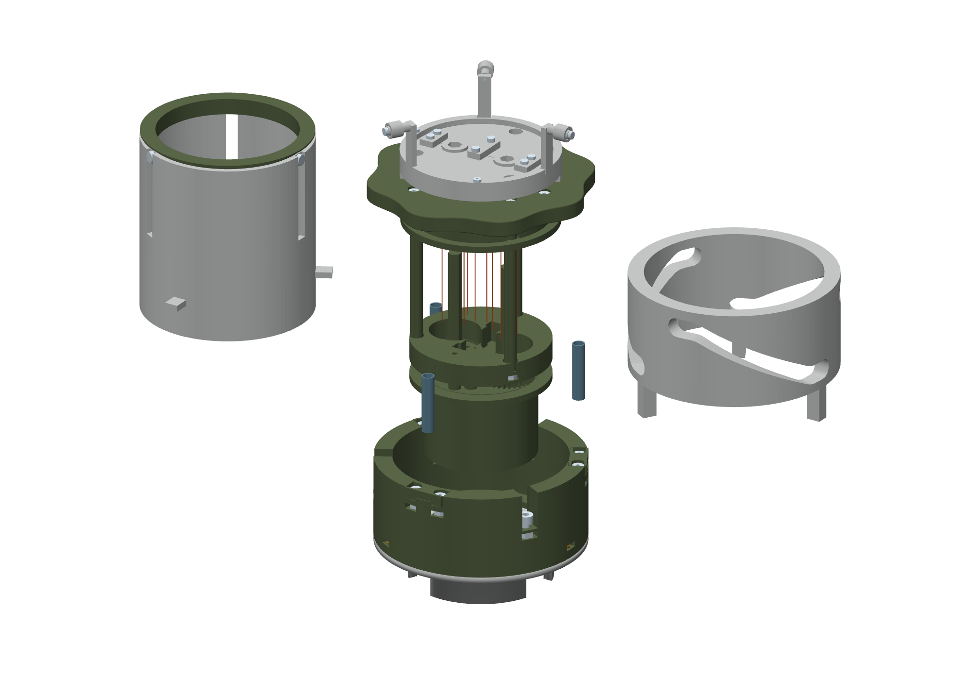
A shell tells half the story.
Take a closer look inside.

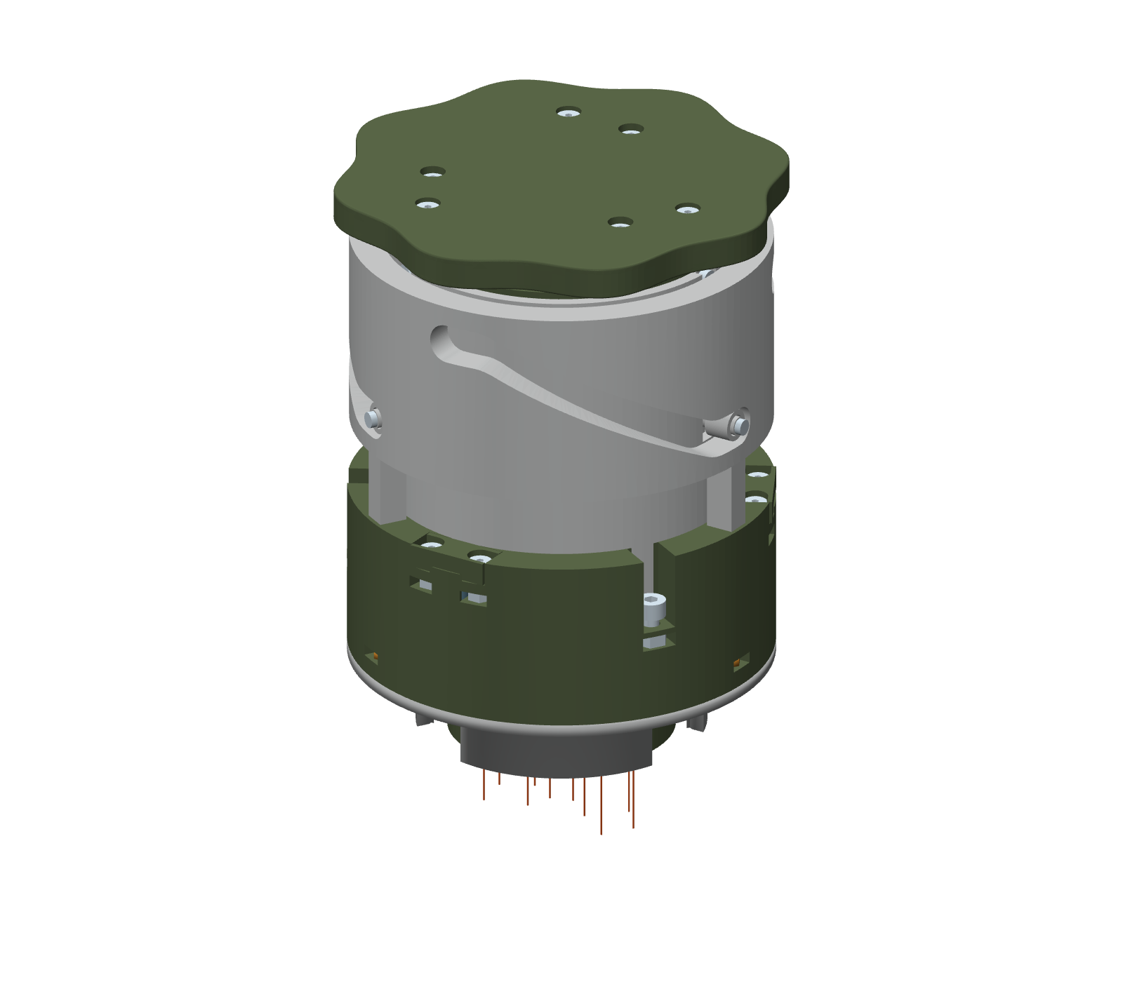
01 / THE EXTERIOR

One considered object.

The grip, sleeve, and body bring three movements into one cylindrical tool.

A / Direct pull and turn

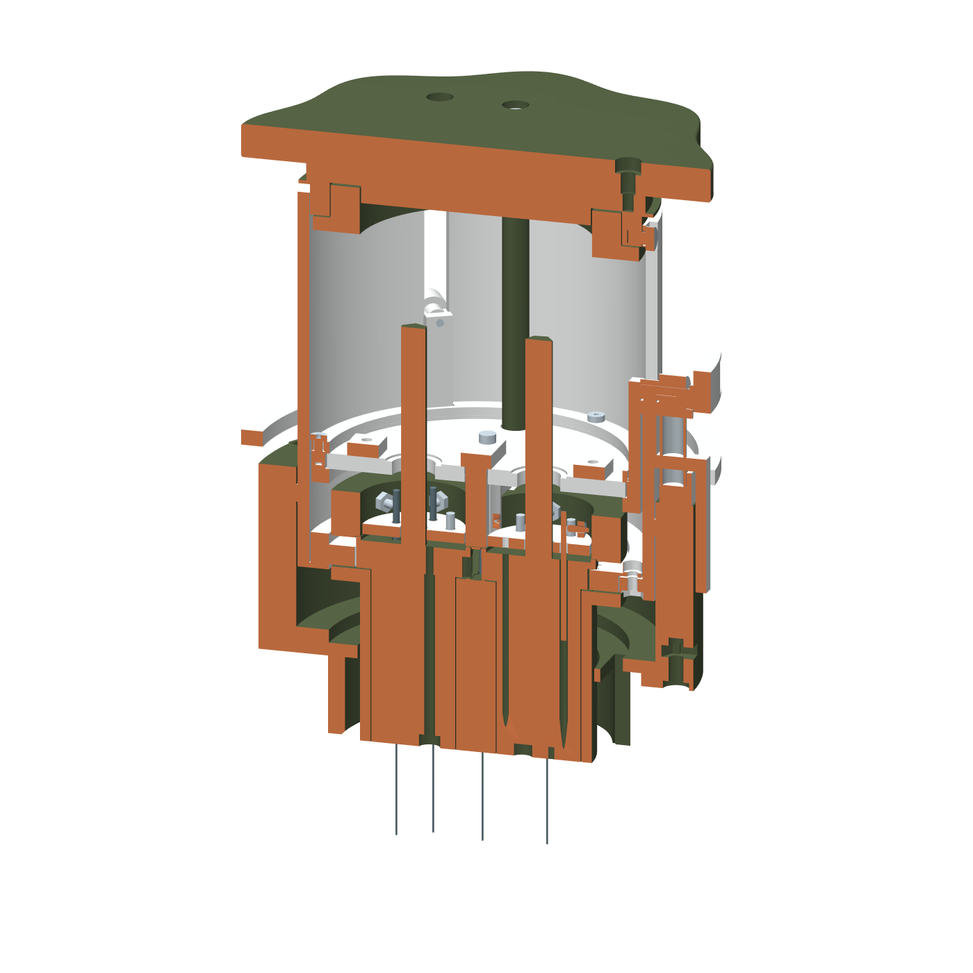
SECTION VIEW
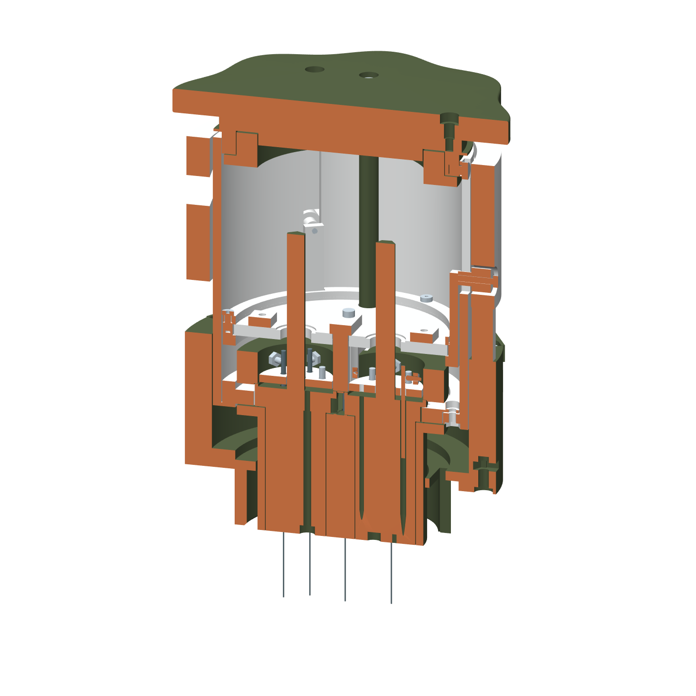
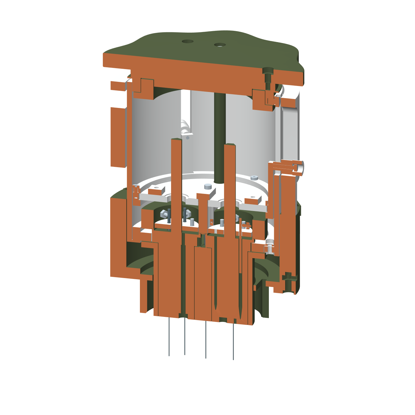
Candidate A: geometric cross section through the Orbit54 mechanism Y = 0.0 MM GEOMETRIC SECTION / C5

Cut through the geometry. Not a stress simulation.

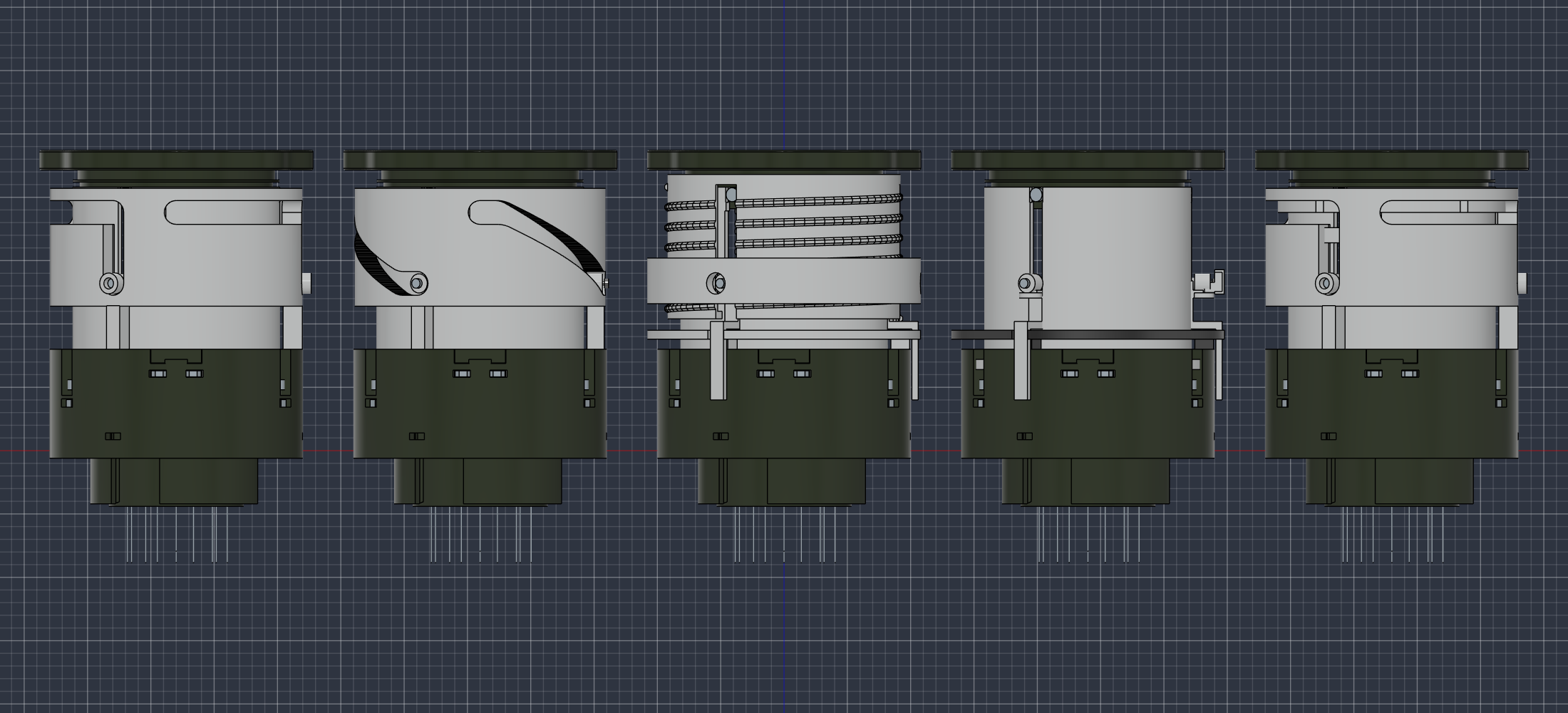
All five Orbit54 C5 assemblies side by side, from A direct pull and turn at left to E orbital drive with cross slides at right
A → E / The five-candidate assemblyOriginal Fusion view · C5 design study

Less choreography.
More considered mechanics.

The work is in getting the motions, clearances, and assembly sequence to agree.

Orbit54 combines Weiss Distribution Technique (WDT)—fine needles moving through the grounds—with a retracting needle mechanism and a tamping face. It is designed around the actual needle inventory: nine 80 mm needles and one 70 mm needle, each with a 0.4 mm working wire.

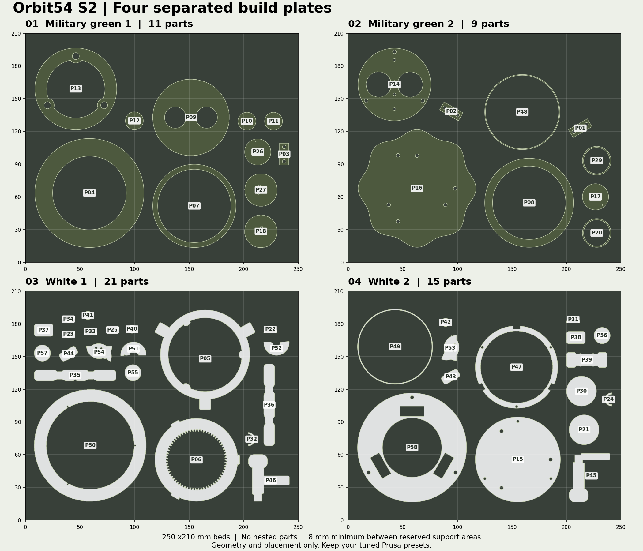
The S2 prototype established the geared mechanism and print plan. The C5 study asks how the same brief could fit into five different cylindrical mechanisms, each with its own assembly and section view.

Compare the five candidates
02 / The C5 design study

Same brief.
Five mechanisms.

Five complete candidates, shown assembled and cut through the center. The study consolidates the S2 design from 56 printed parts to between 25 and 31.

Each still uses 70 fasteners and 10 steel needles. Fewer printed parts are one measure; clearances, motion, and assembly still have to agree.

Every cutaway uses the same Y = 0 plane, camera, and scale. Orange marks cut material. These are geometric sections, not stress simulations.

A

C5 / DESIGN CANDIDATE

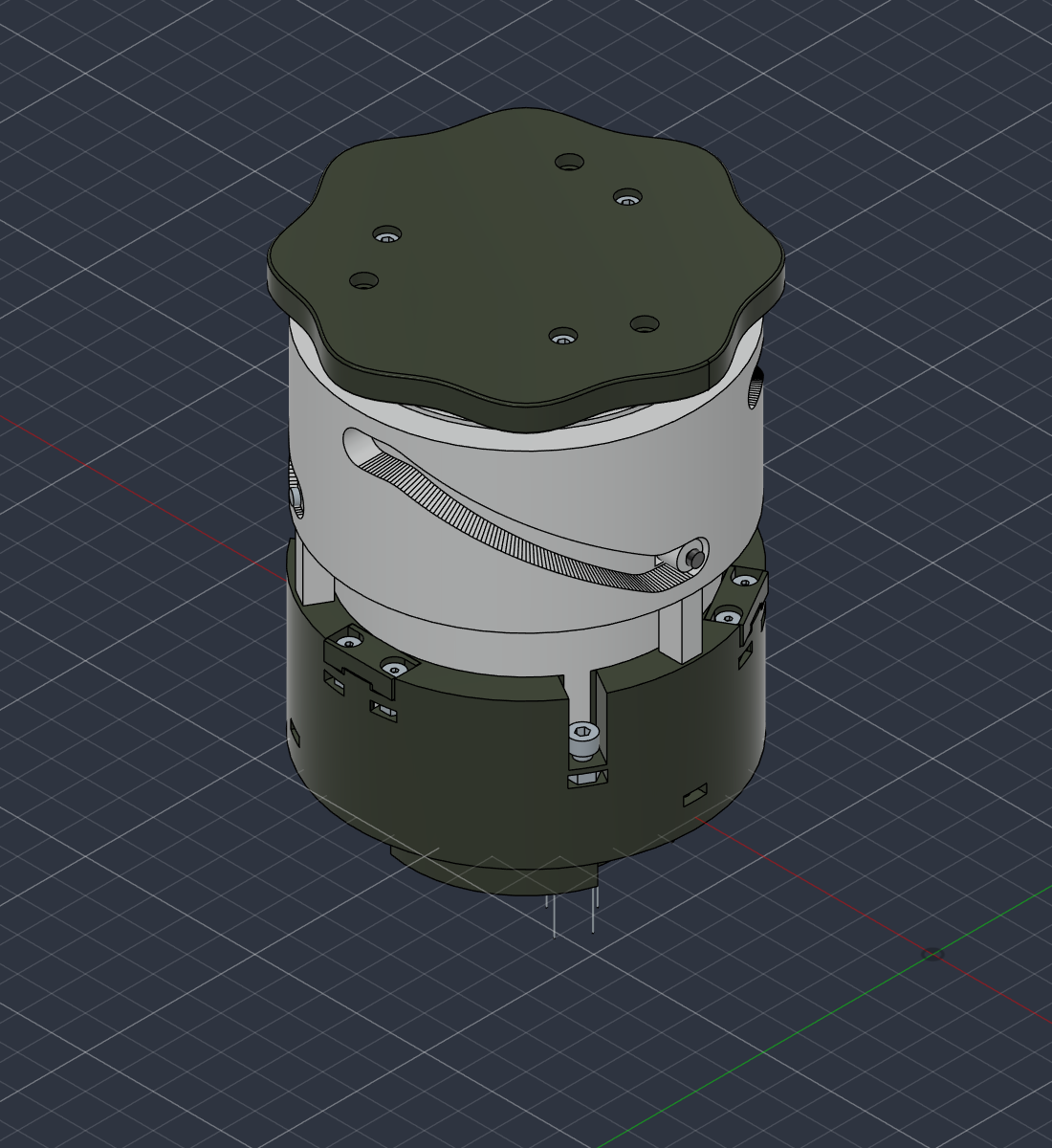
Direct pull and turn

25 PRINTED PARTS / 70 FASTENERS

Lift by hand. Turn to unlock.

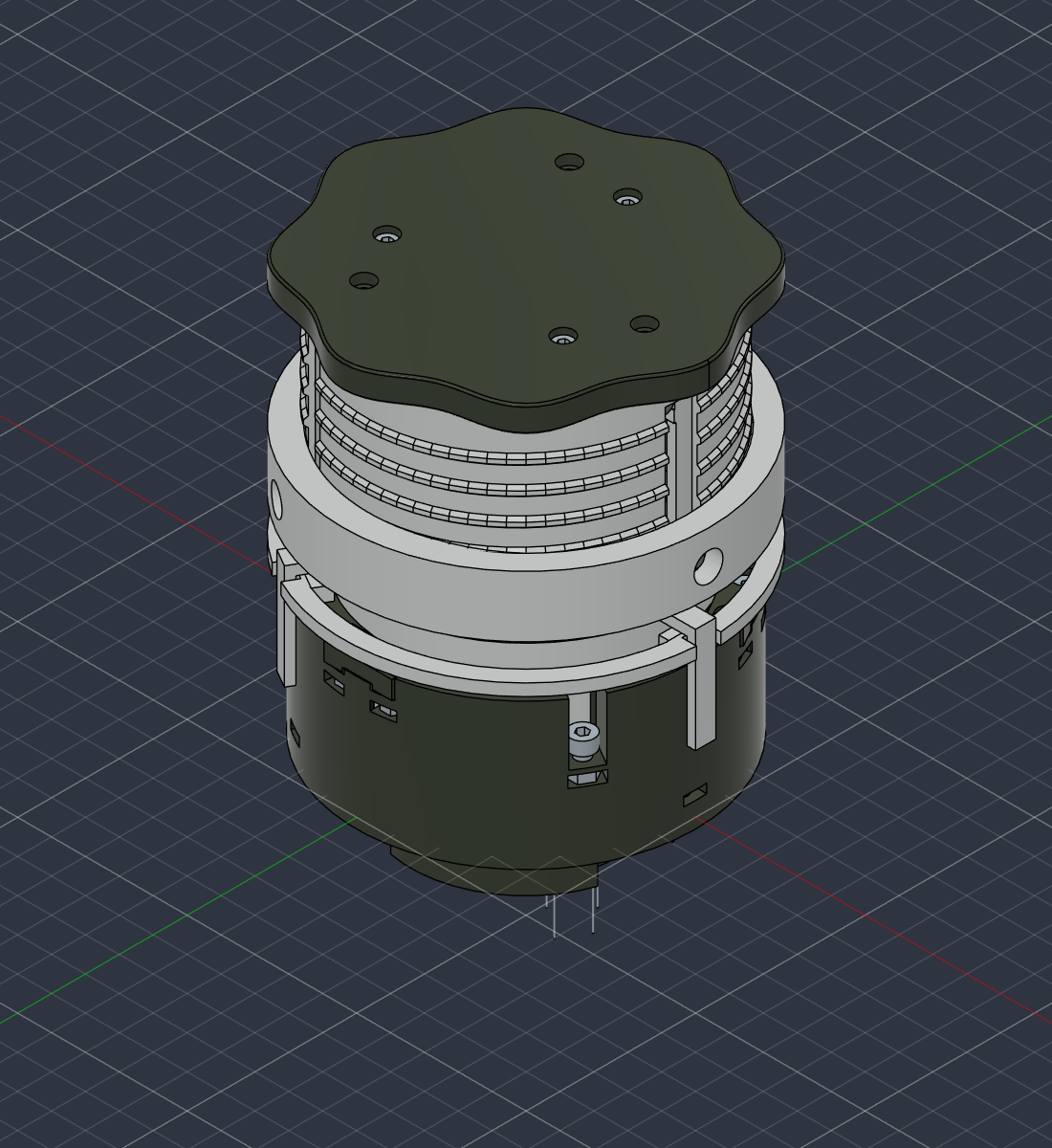
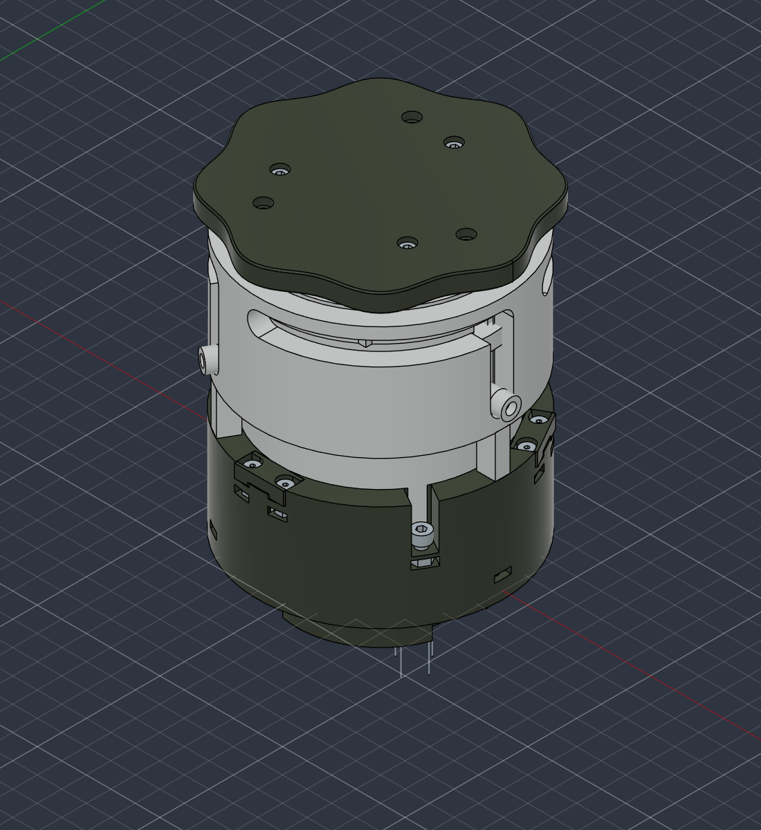
The most direct route through the sequence: pull the needle assembly up, then turn the gate before tamping.
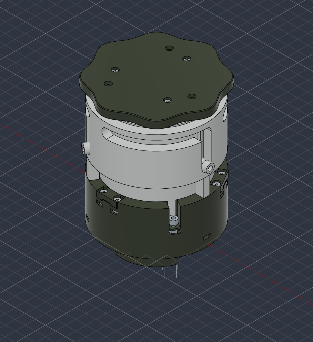
Candidate A, Direct pull and turn: original Fusion assembly view
01 / ASSEMBLYOriginal Fusion view
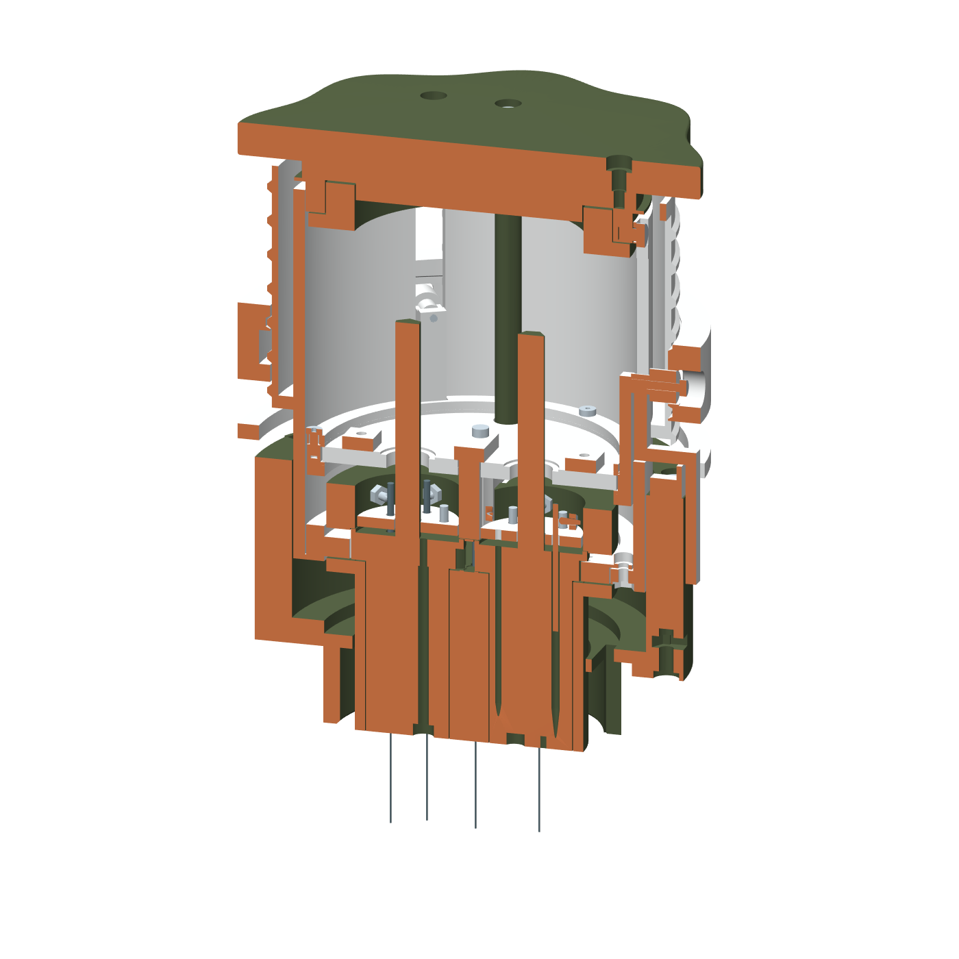
Candidate A, Direct pull and turn: longitudinal CAD cutaway with orange cut faces revealing the internal mechanism
02 / SECTION ANALYSISY = 0 · orange marks the cut

Reading the section

The section opens the concentric sleeves and needle carrier to inspection. The pull path and the gate are separate steps.

Recorded checks

No unintended interference in the complete set of sampled poses. The saved native motion replay also passes.

Clearance: sampled passMotion replay: pass
B

C5 / DESIGN CANDIDATE

Quarter-turn cam

25 PRINTED PARTS / 70 FASTENERS

Let the cam do the lifting.

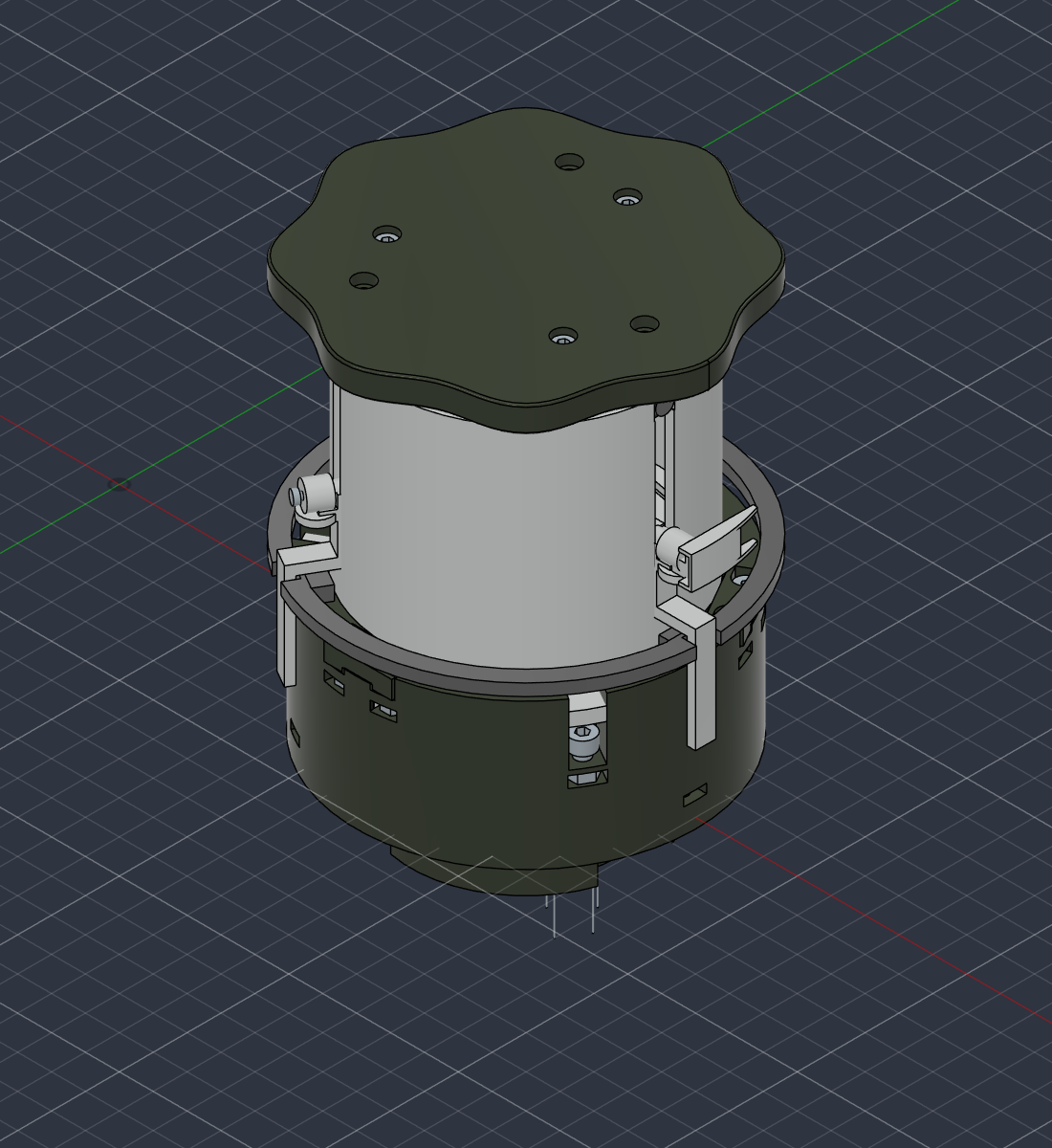
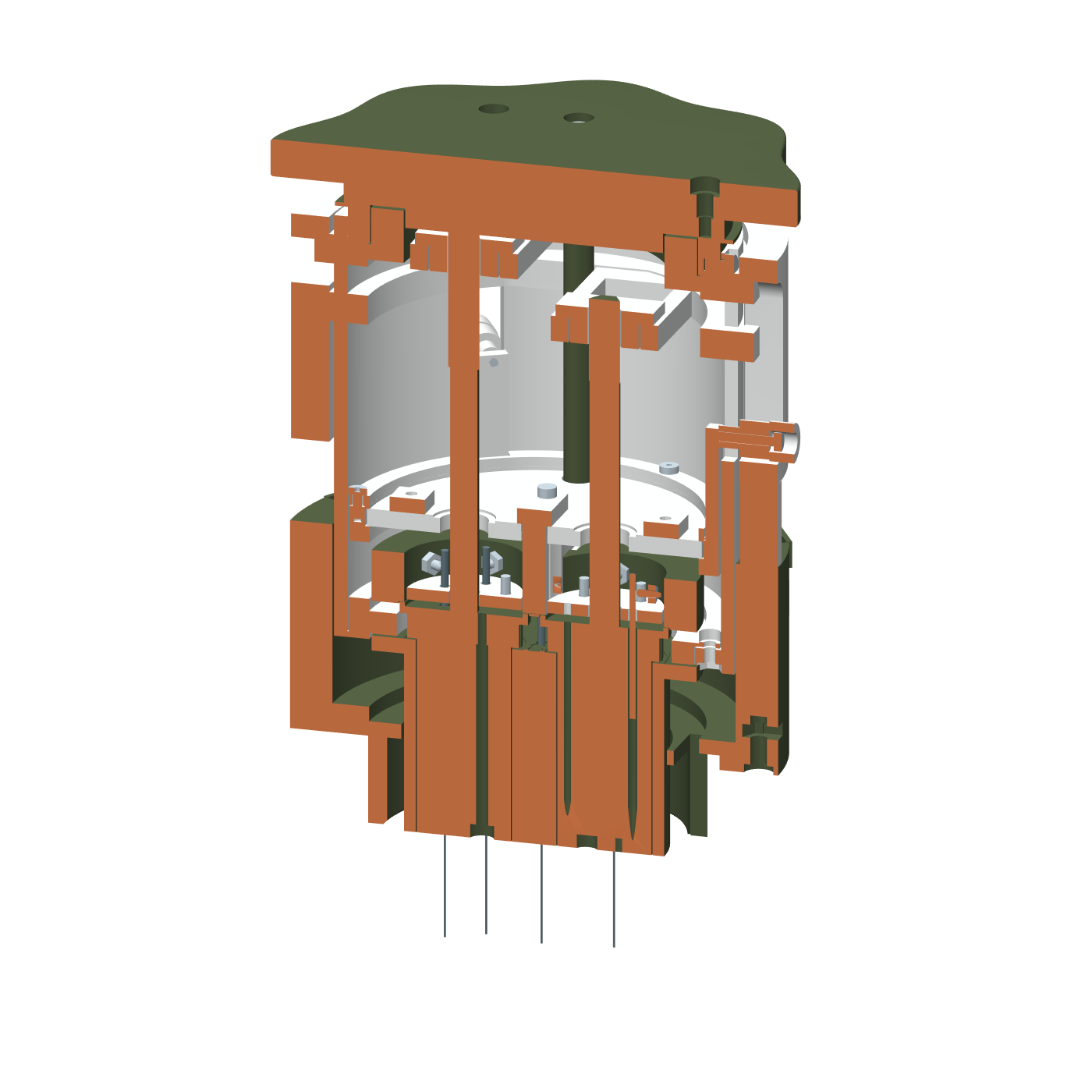
A quarter-turn cam converts rotation into the needle-lifting stroke, keeping the interaction within the cylindrical body.

Candidate B, Quarter-turn cam: original Fusion assembly view
01 / ASSEMBLYOriginal Fusion view
Candidate B, Quarter-turn cam: longitudinal CAD cutaway with orange cut faces revealing the internal mechanism
02 / SECTION ANALYSISY = 0 · orange marks the cut

Reading the section

The sleeve, follower, and nested carrier show how rotation is intended to create axial travel.

Recorded checks

Sampled clearance passes. The detailed native replay records a transform mismatch, so motion agreement remains unresolved.

Clearance: sampled passMotion replay: mismatch
C

C5 / DESIGN CANDIDATE

Threaded lift and gate

26 PRINTED PARTS / 70 FASTENERS

Trade a quick turn for a threaded lift.

A threaded selector raises the mechanism before a separate gate enables the tamping movement.

Candidate C, Threaded lift and gate: original Fusion assembly view
01 / ASSEMBLYOriginal Fusion view
Candidate C, Threaded lift and gate: longitudinal CAD cutaway with orange cut faces revealing the internal mechanism
02 / SECTION ANALYSISY = 0 · orange marks the cut

Reading the section

The cut exposes the threaded lift around the keyed inner cup. Those nested interfaces are the focus of the clearance review.

Recorded checks

Recorded collisions include the cam pin against the keyed cup. The native motion replay also records a mismatch.

Clearance: collisions recordedMotion replay: mismatch
D

C5 / DESIGN CANDIDATE

Spring latch and gate

28 PRINTED PARTS / 70 FASTENERS

Add a spring-assisted latch.

This variation adds a spring-and-latch arrangement to the lift sequence, with a separate gate for tamping.

Candidate D, Spring latch and gate: original Fusion assembly view
01 / ASSEMBLYOriginal Fusion view
Candidate D, Spring latch and gate: longitudinal CAD cutaway with orange cut faces revealing the internal mechanism
02 / SECTION ANALYSISY = 0 · orange marks the cut

Reading the section

The section reveals the additional spring-seat and latch geometry packed around the central assembly.

Recorded checks

Recorded collisions include a clip screw against the lower spring seat. The native motion replay also records a mismatch.

Clearance: collisions recordedMotion replay: mismatch
E

C5 / DESIGN CANDIDATE

Orbital drive with cross slides

31 PRINTED PARTS / 70 FASTENERS

Explore a different distribution path.

An orbital drive and cross slides explore another way to move the needles within the same cylindrical envelope.

Candidate E, Orbital drive with cross slides: original Fusion assembly view
01 / ASSEMBLYOriginal Fusion view
Candidate E, Orbital drive with cross slides: longitudinal CAD cutaway with orange cut faces revealing the internal mechanism
02 / SECTION ANALYSISY = 0 · orange marks the cut

Reading the section

The cut opens up the fixed slide frame and its relationship to the needle mechanism and surrounding body.

Recorded checks

Recorded collisions include a journal screw against the fixed slide frame. The native motion replay also records a mismatch.

Clearance: collisions recordedMotion replay: mismatch

Status labels follow the detailed saved collision and native replay reports. For B, D, and E, the replay reports disagree with the older study summary. No C5 candidate is released for printing; physical testing remains ahead.

03 / The S2 foundation

THREE MOVEMENTS, ONE TOOL
01

Distribute.

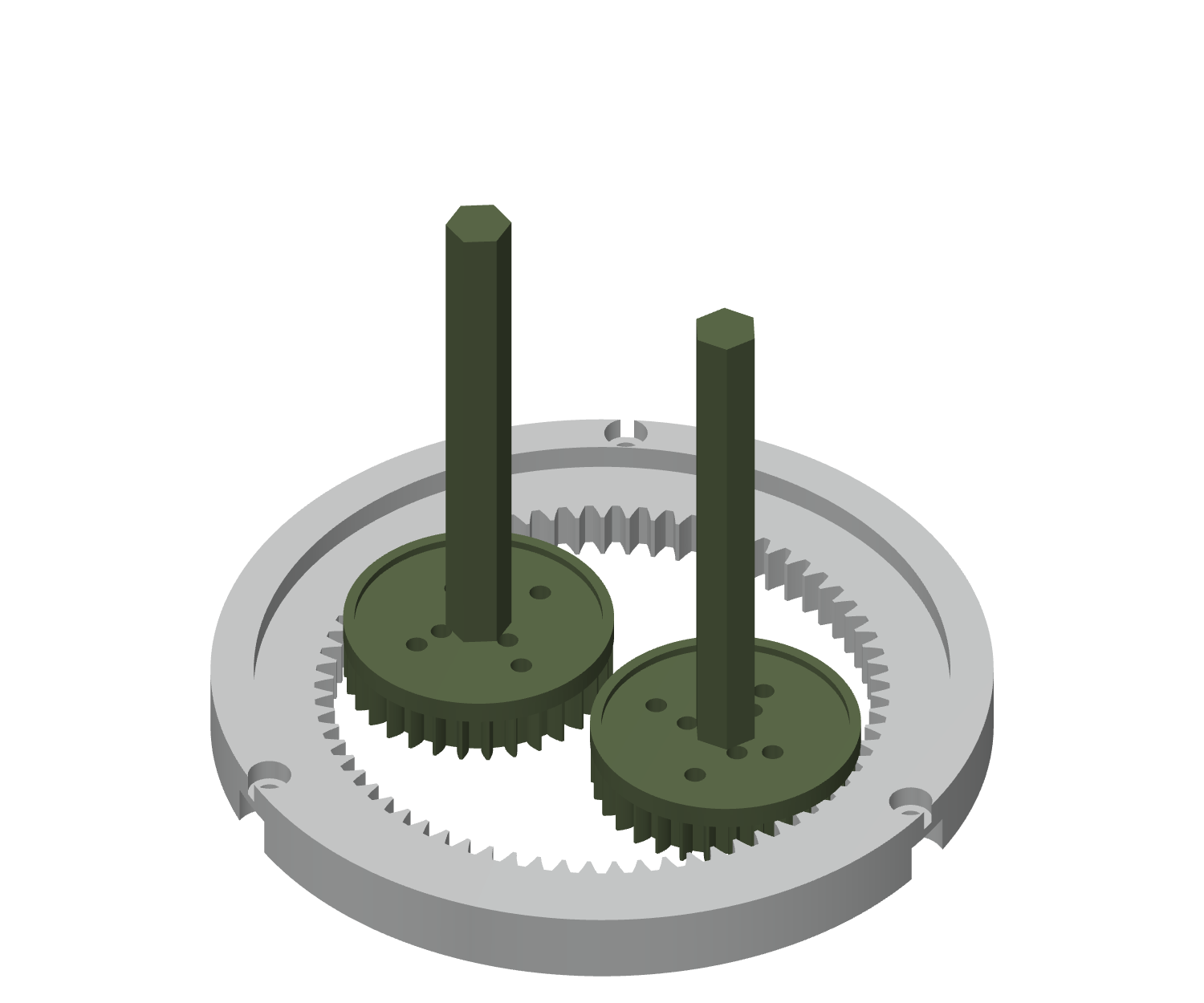
Turn the grip to drive the geared needle holders through the coffee bed.

02

Retract.

The S2 cam mechanism lifts the needles through a modeled 28 mm stroke.

03

Tamp.

With the needles retracted, the tamping face can move into the basket.

A model is a beginning.
The bench is the test.

The C5 study compares mechanisms; the S2 records document the earlier prototype. Physical performance is still to be established.

Checked in the S2 records

  • 56 closed, single-solid print meshes.
  • 40 sampled mechanism poses and 181 sampled assembly operations.
  • 10 continuous needle insertion and withdrawal sweeps.
  • 168 components, 10 joints, and 5 motion links in the Fusion assembly.

Next on the bench

  • Needle retention, guide clearance, and free movement.
  • Spring return, dry cycling, and interlock behavior under load.
  • Funnel registration and gradual tamp-load testing.
  • Coffee performance, cleanability, and contact suitability.

The S2 print plan belongs to the earlier revision. Its checks do not qualify the five C5 candidates. Digital clearance checks and motion replay do not establish physical fit or a load rating.

BACK TO SELECTED WORKMore things, made real.